20 CIVIL WORKS GUIDELINES FOR MICRO-HYDROPOWER IN NEPAL
flow in the rainy season. For diversion from a natural pool, no
weir is required and water can be conveyed through HDPE
pipes or a covered masonry flume to a headrace canal.
For this reason, attempts should be made to locate intakes
such that the natural water level at low flow in the stream is
suitable for the intake level of the canal. This will allow the
canal intake structure to be built at stream level and the only
measures necessary within the stream or river bed itself are
measures for the stabilisation of the present state of the stream.
Location in an area which offers natural protection
When withdrawing water from a stream whose level may
increase markedly during rainy periods, it is desirable to locate
the intake behind or under large, permanently placed boulders
or rock, these limit the water that can enter the intake, and
deflect flood flows and river-borne debris away. Advantage can
also be taken of stable banks and rock outcrops.
Location on the outside of a bend
There is a natural tendency of the river to deposit sediment
on the inside of bends along the river. At bends, the direction
of the flow closest to the river bed changes compared with the
surface flow. A spiral flow forms, which transports the bed
load to the inner side of the river bend. On all streams and
rivers it can be observed that gravel and sand banks form at
the inside bend, i.e., the bed load is diverted from the
deflecting bank. As a result of this when the river flow
decreases, the river width decreases from the inside of the
bend. Therefore an intake should not be sited on the inside
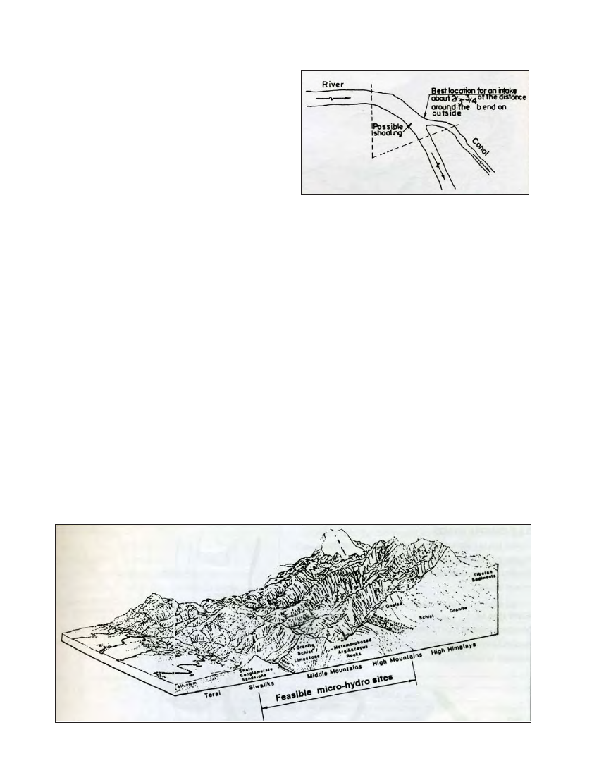
of a bend. To minimise sediment load and to ensure flow
availability during the dry season, an intake should be sited
on the outside of a bend. The best location is about 2/3 to
3/ 4 of the distance around the bend on the outside as shown
in Figure 3.1. Sharper bends are more effective in preventing
the entry of sediment, and the amount of bed load transported
into the canal decreases as the diverted proportion of the
total flow in the river decreases.
Figure 3.1 Locating intake around a bend
Other considerations
In straight sections of a river, the water flows parallel to the banks
and the bed load is transported along the bottom. Therefore, in
straight sections the location of the intake is governed by factors
such as bank stability and headrace alignment.
The location of an intake structure must be so chosen that the
largest possible portion of the bed load remains in the river
and is not diverted into the headrace. However, even a good
intake will not exclude all sediment; the gravel trap and
settling basin further along the canal complete this.
3.3 Intake location in relation to river
characteristics
3.3.1 CHARACTERISTICS OF HIMALAYAN RIVERS
In Nepal, most micro-hydropower schemes are located in the
foothills of the Himalayan Range. This includes the High
Mountains, Middle Mountains and the Siwaliks as shown in
Figure 3.2. It is essential to have a clear understanding of the
characteristics of these Himalayan rivers before approaching
the design and construction aspects of diversion works. These
rivers flow in geologically young mountain structures and
can be characterised as follows:
Figure 3.2 Feasible locations of micro-hydro schemes in Nepal